


- By YIKONG
- 2026-06-04 09:45:49
- Technical
Differential Drive Wheel AGV Motor Sizing Guide Torque Calculation Inertia Matching and Drive System Design
Introduction
The performance of an AGV or AMR system depends heavily on its drive system. Acceleration capability, turning performance, load capacity, and long term stability are all directly influenced by the selection of the drive wheel and motor.
In engineering practice many AGV projects select motors based only on total vehicle weight or previous experience. This approach often leads to insufficient torque during turning or acceleration because a differential drive AGV operates under multiple motion conditions.
A proper design must consider all working conditions including straight motion, curved motion, and in place rotation. Among these conditions in place rotation usually requires the highest torque and becomes the key factor in motor selection.
This document explains the basic engineering method for calculating torque and inertia for differential drive wheel AGVs.
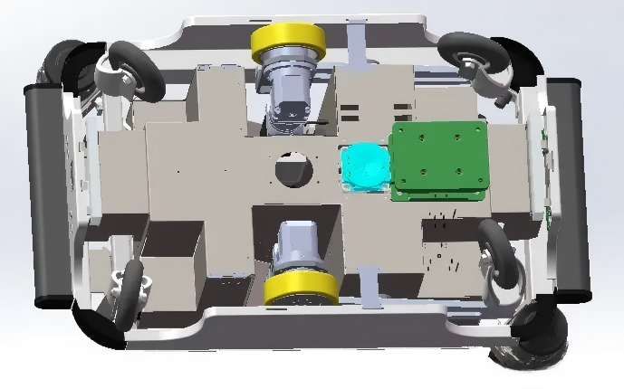
Differential Drive Wheel System Overview
A differential drive AGV typically uses two powered drive wheels and multiple caster wheels for support.
The motion is controlled by changing the speed difference between the left and right drive wheels.
Equal speed results in straight motion.
Different speeds result in turning motion.
Opposite directions result in in place rotation.
This system is widely used in warehouse AGVs AMRs tugger vehicles and industrial mobile robots.
Motion Resistance Components
The total resistance acting on the AGV consists of three main parts.
Rolling resistance
F_roll = (m - m_drive) * g * mu
m is total vehicle mass
m_drive is load supported by drive wheels
mu is rolling resistance coefficient
Acceleration force
F_acc = m * a
a is acceleration of the vehicle
Grade resistance
F_grade = m * g * sin(theta)
theta is slope angle
For flat ground this value is zero
Total driving force
F_total = F_roll + F_acc + F_grade
This force is used as the basis for torque calculation
Straight line operation torque
.webp)
In straight motion both drive wheels share the load equally
Force per wheel
F_straight = F_total / 2
Torque per wheel
T_straight = F_straight * (D / 2)
D is drive wheel diameter
This condition is used for continuous operation verification
In place rotation critical condition
In place rotation is the most demanding condition for a differential drive AGV
During rotation one wheel rotates forward and the other rotates backward
Caster wheels generate high resistance due to steering angles
An engineering approximation of resistance is
F_spin = (2 * F_roll * sqrt(W^2 + L^2)) / W
W is wheel spacing
L is vehicle length
Torque requirement
T_spin = F_spin * (D / 2)
In most real applications rotation torque is two to five times higher than straight line torque
This condition usually determines motor selection
Curved motion condition
Most AGVs operate under curved motion during normal operation
In this case wheel speeds are different and caster wheels generate steering resistance
In general
T_straight < T_curve < T_spin
Curved motion is used for validation of system stability
Load inertia and gear ratio matching
Inertia is an important factor for motion control performance
Equivalent load inertia
J_load = (m / 2) * (D / 2) * (D / 2)
If a gearbox is used the inertia reflected to motor side is
J_motor = J_load / (i * i)
i is gear ratio
Recommended inertia ratio
Servo system below 5 to 1
Stepper system below 10 to 1
Proper inertia matching improves acceleration response stability and control accuracy
Engineering considerations for drive wheel selection
In real applications torque calculation alone is not enough
The following factors must also be considered
wheel traction
gearbox durability
thermal performance
continuous operation time
floor conditions
load distribution
Ignoring these factors may cause wheel slip overheating or unstable motion control
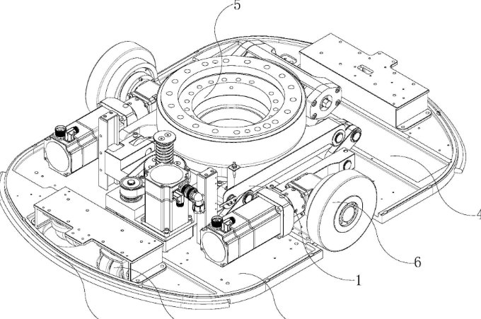
TEC series differential drive wheels
.png)
In practical AGV development integrated drive wheel systems are widely used to simplify design and improve reliability
The TEC series differential drive wheels developed by Yikong Intelligent Equipment integrate low voltage servo motors gearboxes and wheel assemblies into a compact unit
TEC85, TEC240 and TEC550 models are used in
AGVs
AMRs
tugger systems
industrial mobile robots
heavy duty transport platforms
These products help reduce development complexity and improve system consistency
Conclusion
Differential drive AGV motor sizing must be based on multi condition analysis rather than simple weight estimation
Straight motion defines continuous torque requirement
Curved motion validates stability
In place rotation defines maximum torque requirement
Proper torque calculation combined with inertia matching ensures stable and reliable AGV performance in industrial environments