


- By YIKONG
- 2025-03-10 14:28:41
- TECHNICAL
Key points for AGV drive layout and installation
The installation of drives and other drivers in the AGV car body is similar to the electrical control boxes in common mechanical equipment. They have both common points and differences, especially the installation space may be limited, so we mainly consider layout and installation from the following three points.
1. Exit surface and reserved space of a single drive
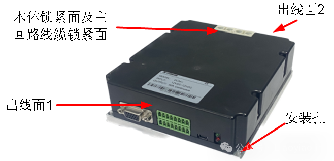
For different brands and models of drives, the first thing we consider is the way of driving ducting, fastening, etc., the driver takes up several sides. The TEC PSM driver is shown in the figure below. The outlet occupies two sides on the front and rear sides. The fastening screws of the main circuit are locked from directly above the driver, so the outlet and tightening of the driver occupy 3 sides. Some qualifiers occupy 3 sides, and with the fastened surface, there are 4 sides. There is another type that all qualifiers come out from the top and then route them from the side up, down, left and right.
After we understand the wiring surface, we must consider the differences in the wiring methods, such as the quick connector terminal output, the wiring terminal output, the DB head and other special terminal output. We must consider the length of the terminal, and also consider whether the terminal needs other tools to lock or disassemble, such as small or Phillips screwdriver, large or Phillips screwdriver, wrench or other special tools. When laying out and designing, you must not only leave the operating space for terminal insertion and locking, but also leave the identification space for wired number identification. Especially, although many dedicated terminals have the same interface, the body has large and small, long and short, and when the space is reserved, it must correspond to the actual terminal size.
2. Arrangement and combination layout of multiple drives
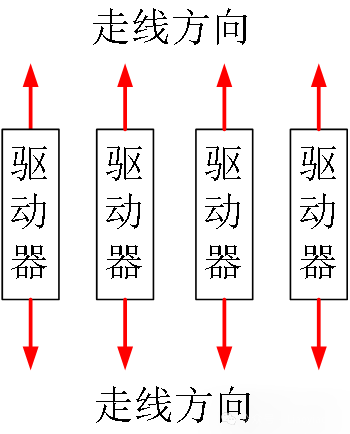
After we have determined the size of each drive and the space required for installation, we will use the AGV body to allow installation space, and meet the distance between multiple drives recommended by the manufacturer to facilitate heat dissipation. Arrange multiple drives from left to right or from top to bottom. The outgoing method is to go up and down or go left and right, and try to ensure horizontal and vertical layout as well as possible.
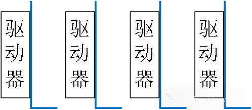
If there is insufficient space for the installation plane, we can arrange multiple drives vertically on the premise of meeting the first point, as shown in the figure below. At this time, we should also try to observe the driver's nameplate mark, status indicator, etc. as intuitively as possible to facilitate future use and maintenance. This layout is very suitable for driver types that include a single side including a wire outlet, an indicator light, a terminal locking surface and a quick-connect terminal. Some drivers have two mounting surfaces themselves. When choosing a small mounting surface, it means that the heat transfer area is smaller, so we must fully consider the impact of the change in the heat dissipation area. As the saying goes, two sides of one body are.
3. Handling and precautions for the installation surface of the drive heat dissipation base
The radiators that come with the drive are mostly made of aluminum, some are flat plates, some are fins, and some are fins and heat dissipation fans. If it is a flat plate, it usually needs to be polished on the driver installation surface and cannot be installed directly on a paint-covered surface (or according to the manufacturer's installation recommendation). During installation, the installation surface and the driver base are uniformly coated with thermally conductive silicone grease, or thermally conductive silicone sheets with the same area as the base, so as to facilitate the dissipation of the driver heat, especially high-power models. If it is equipped with a fan, the fan must be powered as required to run and blow air and heat dissipate. Regardless of the power of the driver, the fixing screws of the driver must be fully locked and locked as required. No shortage of fastening screws, unlocked or foreign objects must be entrained between the driver base surface and the installation surface.
The control signal circuit, main circuit and other high-current circuits also need to be plugged, locked and fixed as required. Do not pull the wires and cables and shake with the AGV car. After each disassembly, check whether they are plugged, locked and fixed when reconnecting to avoid damaging the equipment or operating abnormally.
Summarize:
This article introduces the layout and installation precautions for AGV drives. You must refer to the installation instructions in the drive manual more, because the manufacturer's guidance is suitable for use in most working environments. At the same time, we must also be flexible and adaptable based on our actual situation and do not copy them. If the space in the electronic control box is small and there are many high-power heating equipment, it is recommended to add convection heat dissipation holes or cooling fans to achieve rapid heat dissipation effect. If the driver is through a dedicated terminal debugging interface such as RS232 or 485, it is recommended to connect the relevant communication cable to the general terminal during design. For example, use DB9 terminal to pull out the RS232 communication port to facilitate future debugging, maintenance and other work. The top priority is to analyze specific issues in your work. Please do not simply apply or take some content in the text out of context as your reference.